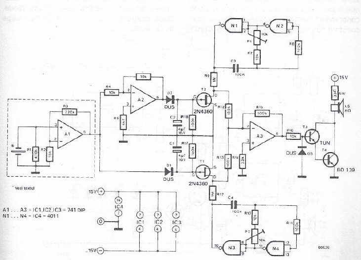
Electronic bell using buzzer
A simple electronic buzzer can be made using electronic diagram below. This circuit produces an "big bang" sound ordered by an piezoelectric element so as to vary both loudness and pause between "big" and "bang." The signal produced by piezoelectric element is firstly amplified by operational amplifier A1. Since the elements have a high piezoelectric ohmic resistance, is the operational amplifier A1 better be embedded in the ring button. Output with low ohmic resistance of A1 can be connected to the rest of the assembly together with power wires in a four-wire cable.
Besides the signal from operational amplifier A1 is available inverted signal from operational amplifier A2 so that push and release of the button is producing a positive pulse. Pulses are used to form the modulated signal which through T1 and T2, modulates the amplitudes of "big" and "bang." Height sounds produced by the two oscillators which are built with two gates of the integrated circuit 4011 can be adjusted with P1 and P2 .


Add new comment