Electrical and electronic circuits tester
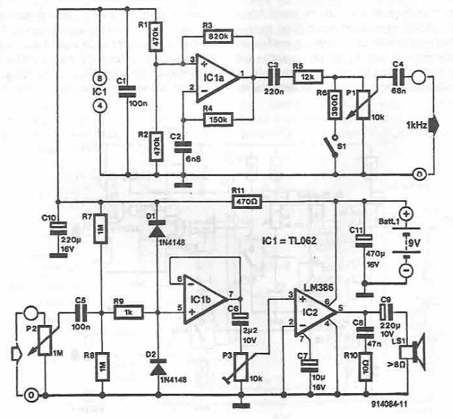
This electronic tester can be used to test electrical and electronic circuits and consists of an oscillator which generates a 1 kHz test signal and a detector which amplify and detects the signal and then make it audible with a small speaker or buzzer. IC1a chip functions as rectangular wave generator frequency determined by R4-C2 time constant. With values from the circuit diagram, the frequency is about 1 kHz and is less affected by supply voltage variations.
Oscillator signal is applied to the test circuit through C3, R5, potentiometer P1 and C4. With a supply of 9 V, maximum voltage on the P1 pointer is 3.5 V. When S1 is closed, the voltage across the output is reduced fourteen times.
Measured signal is brought into the detector sensitivity control potentiometer, P2. The circuit is protected against overvoltage by R9, D1 and D2. After being passed through a buffer stage made with ICIb signal is applied to a level that allows control of a small speaker or buzzer.
The maximum level of control for power amplifier, and therefore maximum power is determined by the setting of P3.


Add new comment